 English
 русский


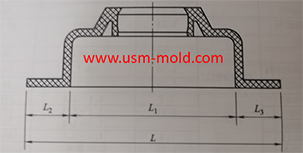
Venting insert design of molded parts
In the thin-walled cavity, the end of the melt flow, the bottom of the blind hole of the mold cavity, the end of the solid column of the plastic part, the bottom of the plastic part rib and screw column, and the corners of the complex cavity are the most where it is easy to cause air trapping, the exhaust in these area mainly depends on the exhaust slot on the shut-off surface between the inserts and the exhaust slot.

Venting design of molded parts:
a. When the end of the material flow is not on the parting surface due to the restriction of the cavity structure, the matching gap between the molded parts can be used to exhaust;
b. Some parts of the forming parts that constitute the cavity, such as ejector rods, ejector pines, moveble parts, etc., the cavity or core are mostly used for clearance fit, and the matching gap is large, if it is designed in the end side of material flow, it can also serve as an exhaust gas, and there is no need to set up an exhaust system at this time;
C. When the exhaust rate cannot meet the requirements, an exhaust structure can be set on the corresponding parts to increase the exhaust rate (see the picture as below);
d. The transitional fitting inserts should have an exhaust slot at the end of the material flow in advance (see the picture as below);
e. The three-stage exhaust slot must be open to the outside of the mold and connected with the air;
f. The exhaust slot between the inserts is easily blocked by plastic powder or mark, and must be cleaned regularly.


Plastic molding shrinkage rate
Dec 30, 2021Plastic parts getting smaller by shrink, due to the temperature decrease during the molding process, and the shrinkage is expressed by the shrinkage rate, it is common plastic shrinkage rates are...view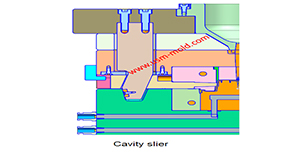
What is the side parting and core pulling mechanisms with their function?
May 31, 2022When there are holes, cavities or cores on the inside or outside of the injection-molded plastic parts that are different from the opening and closing directions of the mold, the plastic parts cannot...view
Vacuum venting mold design for plastic molded parts
Mar 23, 2022There are some regular venting way which are parting surface venting, insert venting, insert pin venting and well-ventilated steel, but there is a special way is vacumm venting, it will need vacumm...view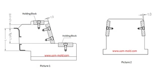
The design requirements of slider wear plate
Jan 2, 20241. The wear plate of slider requires hardening treatment, with a hardness of 45-48HRC; 2. The friction surface of the wear plate is required to be 1.0mm higher than the slider surface (see picture-1);...view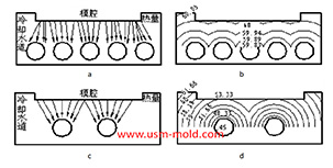
Factors affecting the cooling rate of parts by injection molding
Feb 9, 2022It should be shaped by cooling to get stable plastic part after plastic filling the cavity and core side, so most injection molds need to be equipped with cooling devices to make the mold temperature...view
Slider designing tips 2
Nov 22, 20239. The molding parting surface of the slider molding should be made as a shut-off surface as possible, and the width of the shut-off part should be at least 8mm, and do not make a shut-off surface;...view