 English
 русский

The common fixing method of angle pin
The angle pin is a common part of the drive slider, and the fixing and installation methods as following:
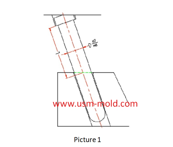
1. Pass through the mold plate directly and press the angle pin with the top plate to fix it, as shown in picture 1.
This installation method is suitable for the case where the formwork is thin and the tope plate is not separated from the A plate, the matching surface is long and the stability is good, the matching tolerance of the angle pin and the fixed plate is H7/m6, disassembly and maintenance are very complex, the mold plate must be disaasembled when changethe angle pin.
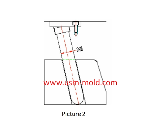
2. Pass through the template directly and press the angle pin with the pressing block to play a fixed role, as shown in picture 2.
This installation method is suitable for the case where the formwork is thin and the top plate is separated from the A plate, the matching surface is long and the stability is good, the matching tolerance of the angle pin and the fixed plate is H7/m6, installation and maintenance are very complex, and the plate must be disassembled to replace the angle pin.
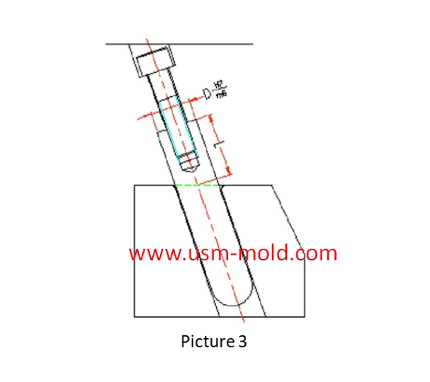
3. The angle pin does not pass through the plate, and the angle pint is still fixed on the plate, but the hole for fixing theangle pin is a blind hole, and a screw is used at the back to tighten the angle pin, this kind of angle pin has no steps, as shown in picture 3.
This installation method is suitable for use in the case of thick plate, and both two-plate and three-plate mold can be used, and the mating surface L needs to be bigger than 1.5D, this installation method has poor stability, and is difficult to process and maintain in the future.
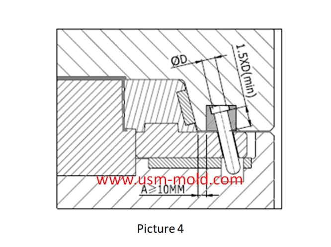
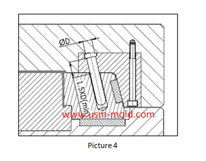
4. The angle pin is not installed in the plate, but is installed in a movable block which is fixed to the plate from the front with screws, the movable block can be disassembled from the front of the plltae, see the picture 4.
This installation method is suitable for use in the case of thick plate, both two-plate with three-plate mold can be used, and the mating surface L needs to be bigger than 1.5D, this installation method has good stability, and is very convenient for processing and maintenance, it is a more common used installation method.
5. The angle pin is not installed in the plate, but is installed in the locking block, this locking block is fixed to the plate from the front with screws, the locking block can be disassembled from the front of the plate, as shown in picture 5.
This installation method is suitable for use in the case of thick plate, both two-plate and three-plate mold can be used, and the mating surface L needs to be bigger than 1.5D, this installation method has good stability, and is very convenient for processing and maintenance, it is also a more common used installation method.


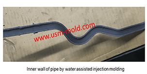
Comparison of water-assisted and gas-assisted injection molding
May 19, 2022Comparing with water-assisted injection molding technology and gas-assisted injection molding technology, the fundamental difference is the nature of the auxiliary molding media used. One is liquid...view
Plastic injection mold runner system design points
Jan 9, 2022When designing the gating system, Firstly, we should consider making the plastic melt fill the cavity with core side quickly to reduce pressure and heat loss; secondly, it should be economically...view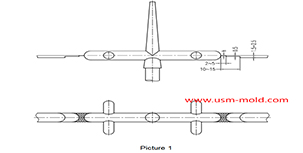
Parting surface venting of runner system
Mar 10, 2022There are a large amount of gas in the main and sub channel, these gas are discharged through the pull rod (push rod) during injection processing, a part of gas come out from exhaust slot on parting...view
Slider spring hength and strength calculation
Apr 22, 2024Processing size: 1. ØD2=ØD+2 2. Ll = total spring length (L) - preload value of spring (N) - slider core pulling distance (L2) Spring length calculation: (refer to picture 1 for length calculation)...view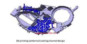
Controling method of plastic injection mold temperature
Feb 15, 2022Except for heat radiation and heat convection from the mold, most of the heat bring into the mold by the plastic needs to be taken out of the mold by the circulating heat transfer medium by heat...view
Vacuum venting mold design for plastic molded parts
Mar 23, 2022There are some regular venting way which are parting surface venting, insert venting, insert pin venting and well-ventilated steel, but there is a special way is vacumm venting, it will need vacumm...view