 English
 русский

Slider spring hength and strength calculation
Processing size:
1. ØD2=ØD+2
2. Ll = total spring length (L) - preload value of spring (N) - slider core pulling distance (L2)
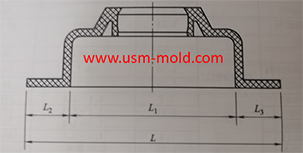
Spring length calculation: (refer to picture 1 for length calculation)
★L≥H/(36%(compression percentage)-10%(pre-compression percentage)
Assuming the core pulling distance (L2)=15m, the total length of the spring L≥15/(36%-10%)=15/0.26=57.7
As we can see that the total length of the spring (L) should be taken as 60mm
Spring hole depth L1=L-L*10%-L2=60-60*10%-15=39mm

Strength requirements of the slider spring:
1. When the spring is applied to the core pulling of the slider, the load strength must be checked;
2. The weight of the slider on the top side must be kept within 2/3 of the maximum load of the spring; the weight of other sliders must be kept within the maximum load of the spring;
3. When the same slider uses multiple springs, the maximum spring load of the slider is the sum of the loads of all springs;
4. When calculating the maximum load of the slider spring, the compression amount should be in the pull-out state of the slider;
The spring load is calculated as follows:
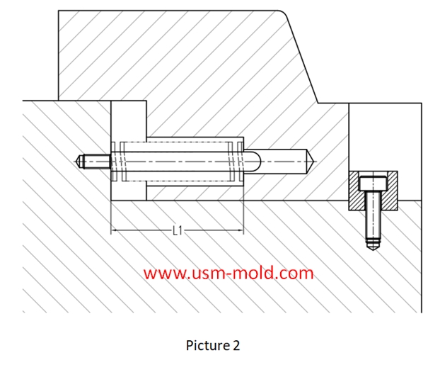
Picture 2:
1. The slider is in the extracted state, so the length of the spring after being compressed is L1;
2. Assume that the free length of the spring is L;
Calculation way of spring load: load = spring constant X compression
That is: load = spring constant X (L-L1)
The spring constant can be obtained from the standard parts data of the corresponding brand (such as MISUMI);

_20250310164515A048.webp "Touch Switch Sensor Mold")

Plastic molding shrinkage rate
Dec 30, 2021Plastic parts getting smaller by shrink, due to the temperature decrease during the molding process, and the shrinkage is expressed by the shrinkage rate, it is common plastic shrinkage rates are...view
Conformal cooing channel of plastic injection mold
Feb 23, 2022The conformal cooling gate is a new type of mold cooling gate based on 3D printing technolog, because of its processing characteristics, the conformal cooling gate can fit the shape of the product...view
The design principle of the exhaust slot
Mar 6, 2022The exhaust system of plastic molds is also very important, if the product has air trapping or exhaust system is not suitable will have a big impact on injection molding production and product...view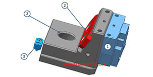
Slider designing tips 1
Aug 3, 20221. After the slider core pulls out, the length of staying in the guide pin slot should not be less than 2/3 of the total length of the slider, for special cases, the slider slot can be partially...view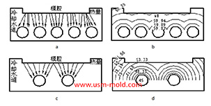
Factors affecting the cooling rate of parts by injection molding
Feb 9, 2022It should be shaped by cooling to get stable plastic part after plastic filling the cavity and core side, so most injection molds need to be equipped with cooling devices to make the mold temperature...view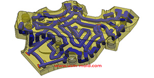
Plastic cooling factors by injection parameter
Feb 10, 20221. Plastic parts design: mainly for the wall thickness of plastic products. The thicker thickness of the product, the longer the cooling time. Generally speaking, the cooling time is approximately...view