 English
 русский

Gas-assisted Injection Molding Equipment

The gas-assisted equipment includes a gas-assisted control part and a nitrogen generator, it is special and seperate system of the injection molding machine, and its only interface with the injection molding machine is the injection signal connection line. After the injection molding machine transmits an injection signal injection start or screw position to the gas-assisted control unit, it starts a gas injection process, and when the next injection process starts, another injection signal is given, and another cycle starts and so on. The gas used in gas-assisted injection molding must be an inert gas (usually nitrogen), the maximum pressure of the gas is 35MPa, and the maximum pressure of the gas can be up to 70MPa, and the nitrogen purity is ≥98%. The gas-assisted control part is a device that controls the gas injection time and pressure, it has a multi-group gas circuit design that can control the gas-assisted production of multiple injection molding machines at the same time, the gas-assisted control part has a gas recovery function to reduce gas as much as possible consumption.


_20250310164515A048.webp "Touch Switch Sensor Mold")

Insert pin of vengting design for molded parts
Mar 20, 2022Insert pin of venting: It is difficult to make exhaust slot when end runner is not in parting surface during injection, and there is no matching gap available, but we could make the venting pin at end...view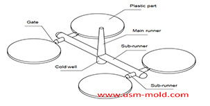
Design principles of plastic injection mold runner system
Jan 6, 20221. Quality first The design of the gating system has a big influence on part quality, firstly the gate should be set at the easiest part of the plastic part to be removed, and at the same time, the...view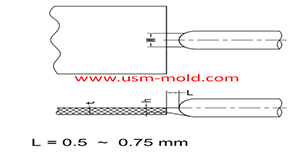
Plastic injection mold runner system design
Jan 16, 2022The gate is the connecting part between the runner and the cavity, and is also the end part of the injection mold gating system, the molten plastic enters the cavity and core side through the gate...view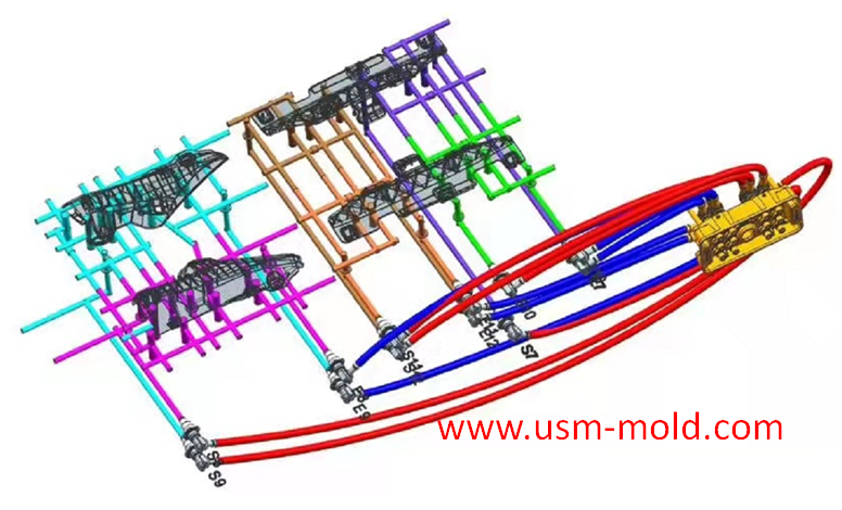
Temperature system of injection mold
Feb 8, 2022Hi everyone,the mold cooling time is the longest during injection, so the design of mold temperature system controlling is very important, we will talk about mold cooling, heating system in following...view
What is Called Draft Angle?
Dec 29, 2021The draft angle is also called demold angle and angle which is used for product removal from the mold and designed on the parting surface, the angle is called draft angle which shows in picture 1....view
Plastic molding shrinkage rate
Dec 30, 2021Plastic parts getting smaller by shrink, due to the temperature decrease during the molding process, and the shrinkage is expressed by the shrinkage rate, it is common plastic shrinkage rates are...view