 English
 русский

Design standard of exhaust slot
The exhaust system should ensure that the gas in the cavity is smoothly discharged, and also prevent the material from entering and exhausting channels from causing flashing of the product or blockage of the gas channel during mass production, most plastic mold factories and plastic mold suppliers only know that they need to open an exhaust slot, but they don’t how large is reasonable. So the cross-sectional size design at the entrance of the exhaust system is very important, in order to meet the above requirements, the inlet section of the exhaust system is usually designed as a gap with a larger aspect ratio (h/w) (see pictue 1), and the gap depth (exhaust gap or exhaust slot depth) h, which is less than the overflow value of the material into the mold is limited, generally 0.02-0.05mm; the gap width w is determined according to the gap depth H and the cross-sectional area A of the exhaust passage required to discharge the gas in the mold cavity during the filling time (w≥A /h).

The cross-sectional area A of the exhaust channel is calculated as follows: A=0.05V/N
In the formula: A exhaust channel cross-sectional area mm²
V—total volume of cavity and pouring system, cm³
n——the number of exhaust slots

The overflow value is the smallest gap that the material can flow into, the overflow value of the molding material depends on the fluidity of the material determined by the material characteristics and process conditions. The better the fluidity, the smaller the overflow value, tThe overflow values of commonly used plastics and conventional molding conditions are shown in picture 2 in the following table.
Picure 3 shows the design standard of the exhaust slot, and picture 4 shows the wrong opening method of the exhaust slot.


Plastic cooling factors by injection parameter
Feb 10, 20221. Plastic parts design: mainly for the wall thickness of plastic products. The thicker thickness of the product, the longer the cooling time. Generally speaking, the cooling time is approximately...view
Gas-assisted Injection Molding Equipment
Apr 10, 2022The gas-assisted equipment includes a gas-assisted control part and a nitrogen generator, it is special and seperate system of the injection molding machine, and its only interface with the injection...view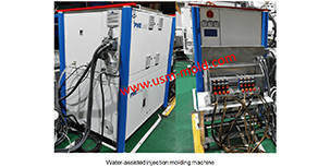
Water assisted injection molding introduction
May 11, 2022Like the gas-assisted injection molding process, water-assisted injection molding injects a piece of plastic into the mold cavity and core firstly, and then injects water to squeeze the melt plastic...view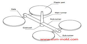
Design principles of plastic injection mold runner system
Jan 6, 20221. Quality first The design of the gating system has a big influence on part quality, firstly the gate should be set at the easiest part of the plastic part to be removed, and at the same time, the...view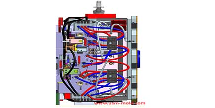
Plastic injection mold cooling system design notice
Feb 14, 2022Design notice of designing the cooling system: 1. Normal molds can be quickly cooled to obtain a shorter molding cycle, and precision molds can be slowly cooled with a mold temperature thermometer; 2....view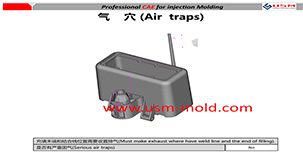
Reasons for making the exhaust system of the injection mold
Feb 28, 2022The gas in the injection mold includes not only the air in the cavity, but also the air in the gate and the decomposition gas generated by the plastic melt, and the steam which caused by plastic in...view