 English
 русский

The difference between full shot and short shot of gas-assisted injection molding
Gas-assisted injection molding can be divided into short shot and full shot.
- Short shot
The short shot method is shown in picture 1, it is suitable for thick-walled plastic parts with low mold filling resistance, especially rod-shaped parts, which can save a lot of raw material, we should inject part of resin into the cavity and core (usually only fills 50% volume of caity and core) during the short shot, and immediately inject gas into the center of the resin, push the gas and obtain a hollow plastic part, For thin-walled plastic parts with high mold filling resistance, it’s better to use full shot molding.
For short shots, the percentage and prolong time of plastic melt fills the cavity and core before the gas injected are the main factors to control the length of the gate channel, in addition, the further shrinkage of the plastic will make the channel continue to be longer, if too much plastic is injected at early stage, it will cause the gas flow length is not enough, but if too little plastic is injected, the gas will quickly penetrate the plastic flow front and cause waste.

2. Sub-cavity method (full shot)
The secondary cavity molding method, it is also called the overflow well method, it is a kind of full shot process (as shown in picture 2). the secondary cavity method requires a secondary cavity that can connect with the mold cavity in outside, the secondary cavity follows the main cavity, the valve needle between the cavities is opened or closed by the hydraulic cylinder or air cylinder, first, close the sub cavity, inject plastic melt into the cavity until the cavity and core is full, then open the sub cavity, and inject gas into the cavity, the penetration of gas pressure causes the excess melt to flow into the secondary cavity, when the gas penetrates to a certain extent, the secondary cavity is closed, and the gas pressure continues to increase to maintain pressure and feed the melt in the cavity with core side, and finally open the mold to eject products.


_20250310164515A048.webp "Plastic Box Mould")
Limitations of gas-assisted injection molding technology
Apr 25, 2022Gas-assisted injection molding technology has obvious advantages in thick wall thickness and pipe parts, but this technology still has many limitations, which are mainly reflected in the following...view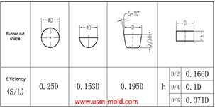
Hydraulic diameter conversion of runners in plastic mold gating system design
Jan 13, 2022Hydraulic diameter refers to 4 times the ratio of the flow cross-sectional area to the perimeter, as the wall shear stress of non-circular pipes is not even distributed along the surrounding walls,...view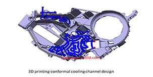
Controling method of plastic injection mold temperature
Feb 15, 2022Except for heat radiation and heat convection from the mold, most of the heat bring into the mold by the plastic needs to be taken out of the mold by the circulating heat transfer medium by heat...view
Pin-point gate of plastic injection mold runner system design
Jan 24, 2022In order to get the best injection quality, the gate type must be selected carefully, the coommon gate tyeps are: direct gate, side gate, pin-point gate, sub gate,valve gate of hot runner etc. Among...view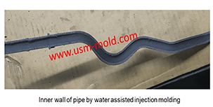
Comparison of water-assisted and gas-assisted injection molding
May 19, 2022Comparing with water-assisted injection molding technology and gas-assisted injection molding technology, the fundamental difference is the nature of the auxiliary molding media used. One is liquid...view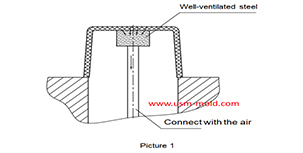
Well-ventilated steel of venting design for molded parts
Mar 14, 2022Well-ventilated steel is a sintered alloy, iIt is a porous material sintered with spherical particle alloys, the pore size is 7-10μm and the strength is poor, but the texture is loose which allow the...view