 English
 русский

Slider designing tips 1

1. After the slider core pulls out, the length of staying in the guide pin slot should not be less than 2/3 of the total length of the slider, for special cases, the slider slot can be partially lengthened;
2. In principle, the length of the sliding part of the slider should be bigger than 1.5 times the height of the slider;
3. The mating surface of the cross-section surface of the slider going deep into the fixed die is made into a side slope of 3~5° to avoid air or unilateral, as shown in 1 in picture 1;
4. The maximum angle of the angle pin shall not exceed 22°,, and the wedge angle of the slider is 2-3° larger than that of the angle pin;
5. The entrance of the angle pin hole of the slider should be made into an R angle, as shown in 2 in picture 1;
6. The matching gap between the angle pin hole of the slider and the angle pin should be avoided by 0.5-1.0mm on one side;
7. After the slider is pulled out, there must be a stroke switch, and the slider limit device with a compression spring and a stop is preferred, as shown in 3 in picture 1;
8. A wear plate is required for the locking part of the slider, as shown in 4 in picture 1, the slider and the top of the entrance of the locking block make an R angle.

_20250310164515A048.webp "Plastic Switch Mould")

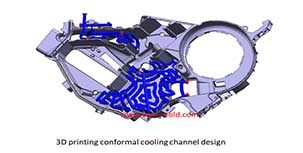
Controling method of plastic injection mold temperature
Feb 15, 2022Except for heat radiation and heat convection from the mold, most of the heat bring into the mold by the plastic needs to be taken out of the mold by the circulating heat transfer medium by heat...view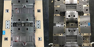
What is Plastic Injection Mold?
Dec 27, 2021The plastic mold is used for injection molding, it is assembled with cavity, core and side slider together, with ejection system and adjustments to produce plastic products by different shapes and...view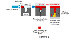
The main reasons for air trapping of plastic injecton mold
Mar 1, 2022During the injection molding process, the front end of the slight ribs may be air trapped and plastic burnt, and also cause the molded part may become black and carbonized. The mechanism of air...view
Slider spring hength and strength calculation
Apr 22, 2024Processing size: 1. ØD2=ØD+2 2. Ll = total spring length (L) - preload value of spring (N) - slider core pulling distance (L2) Spring length calculation: (refer to picture 1 for length calculation)...view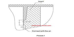
Venting insert design of molded parts
Mar 13, 2022In the thin-walled cavity, the end of the melt flow, the bottom of the blind hole of the mold cavity, the end of the solid column of the plastic part, the bottom of the plastic part rib and screw...view
What is Called Draft Angle?
Dec 29, 2021The draft angle is also called demold angle and angle which is used for product removal from the mold and designed on the parting surface, the angle is called draft angle which shows in picture 1....view