 English
 русский

Design principles for wall thickness of plastic products
The principles of wall thickness design for plastic parts are as follows:
1. Making the wall thickness even is the first principle of plastic part design, it can make filling, cooling and shrinking even, good molding, high dimensional accuracy and high productivity. If the wall thickness can not be even due to some special requirements of plastic parts, the inclined plane should be used to gradually transition between the thick and thin walls. In addition, the ratio of thickness must be strictly controlled as follows: thermosetting plastic: pressing 1:3, extruding 1:5 thermoplastic: injection molding 1: (1.5~2);
2. Under the conditions of meeting the requirements of the structure and use of the plastic parts, use a smaller wall thickness as much as possible, so that we can get: the mold cools quickly, the part weight is light and saving material:
3. The design of the wall thickness of the plastic part should be able to withstand the impact and vibration of the mold ejection device, etc.;
4. There must be sufficient thickness at the connection and fastening place of the plastic part, the place where the insert is buried, and the junction of the plastic melt at the hole (welding mark);
5. When determining the wall thickness, the required strength during storage and handling must be considered;
6. To meet the wall thickness required for melt filling during molding, it is necessary to avoid insufficient filling or thin walls that are easy to burn, but also to avoid melt fracture or thick walls that are easy to produce depressions;
7. Different plastics have different reasonable wall thicknesses due to their different fluidity, see list 1 for details;
8. The fire rating required by the product, different fireproof grades correspond to different product wall thicknesses, if the product wall thickness has been determined, in order to achieve the required fireproof grade, it is often necessary to replace higher grade materials, if there is no suitable material, then it needs to be increased product wall thickness.

_20250310164515A048.webp "Plastic Box Mould")

Controling method of plastic injection mold temperature
Feb 15, 2022Except for heat radiation and heat convection from the mold, most of the heat bring into the mold by the plastic needs to be taken out of the mold by the circulating heat transfer medium by heat...view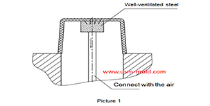
Well-ventilated steel of venting design for molded parts
Mar 14, 2022Well-ventilated steel is a sintered alloy, iIt is a porous material sintered with spherical particle alloys, the pore size is 7-10μm and the strength is poor, but the texture is loose which allow the...view
Pin-point gate of plastic injection mold runner system design
Jan 24, 2022In order to get the best injection quality, the gate type must be selected carefully, the coommon gate tyeps are: direct gate, side gate, pin-point gate, sub gate,valve gate of hot runner etc. Among...view
Different treatment of plastic injection mold cooling system principles
Feb 22, 2022Different treatment principle: 1. The mold temperature is different according to the different plastics, when the plastic requires the molding temperature of the mold to be ≥80°C, the mold must be...view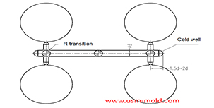
Key points of plastic injection mold runner system
Jan 12, 2022The sub-runner is a transitional channel between the main runner and the gate, as the sub-runner is the longgest part of gating system, so it is very important to enhance the parts quality and improve...view
Design Tips of Vacuum Venting Mold
Mar 30, 2022There are some regular venting way which are parting surface venting, insert venting, insert pin venting and well-ventilated steel, but there is a special way is vacumm venting, it will need vacumm...view